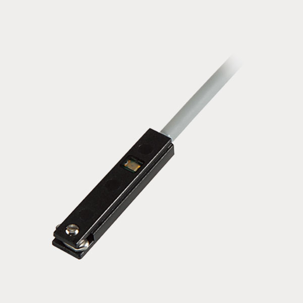
CS-40R, CS-40N, CS-40P, CS-40RP
SPECIFICATIONS
| Type | CS-40R | CS-40N | CS-40P | CS-40RP |
| Wiring Method | 2-Wire Type | 3-Wire Type | 3-Wire Type | 3-Wire Type |
| Switching Logic | SPST, Normally Open | Solid State Output, Normally Open | Solid State Output, Normally Open | SPST, Normally Open |
| Sensor type | Reed Switch | NPN Current Sinking | PNP Current Sourcing | Reed Switch |
| Operating Voltage | 5~120V DC/AC | 10~30V DC | 10~30V DC | 10~30V DC/AC |
| Switching Current | 100mA max. | 100mA max. | 100mA max. | 500mA max. |
| Contact Rating (NOTE 1) | 10W max. | 3W max. | 3W max. | 10W max. |
| Current Consumption | - | 8mA@24V DC max. | 8mA@24V DC max. | 10mA@24V DC max. |
| Voltage Drop | 3.5 V max. | 1.5 V max. | 1.5 V max. | 0.1 V@100mA max. |
| Leakage current | - | 0.01 mA max. | 0.01 mA max. | - |
| Indicator | Red LED | Red LED | Yellow LED | Yellow LED |
| Cable | Ø3, 2C, PUR | Ø3, 3C, PUR | Ø3, 3C, PUR | Ø3, 3C, PUR |
| Operating Frequency | 200Hz | 1000Hz | 1000Hz | 200Hz |
| Magnet Requirement (NOTE 2) | 50 Gauss Parallel | 45 Gauss Parallel | 45 Gauss Parallel | 45 Gauss Parallel |
| Temperature Range | -10~70℃ (+14~158℉) | -10~70℃ (+14~158℉) | -10~70℃ (+14~158℉) | -10~70℃ (+14~158℉) |
| Shock (NOTE 3) | 30 G | 50 G | 50 G | 30 G |
| Vibration (NOTE 4) | 9 G | 9 G | 9 G | 9 G |
| Enclosure Classification | IEC 60529 IP67 (NEMA6) | IEC 60529 IP67 (NEMA6) | IEC 60529 IP67 (NEMA6) | IEC 60529 IP67 (NEMA6) |
| Protection Circuit (NOTE 5) | 1 | 2, 3, 4 | 2, 3, 4 | 1 |
NOTE:
- WARNING: Never exceed rating (Watt=Voltage x Amperage). Permanent demage to sensor will occur.
- Measuring standard target: ø15.5Xø8X5t (Anisotropy rubber magnet)
- Sin wave / X , Y , Z 3 directions / 3 times each direction / 11 ms each time.
- Double amplitude 1.5 mm / 10Hz~55Hz~10Hz (Sweep 1 min) / X , Y , Z 3 directions / 1 hour each time.
- 1=None / 2=Short-circuit / 3=Power Source Reverse polarity / 4=Surge Suppression